Hydraulic systems rely on a variety of specialized components to ensure smooth and efficient operation. Two crucial components that often appear in hydraulic schematics are check valves and shuttle valves. These valves play vital roles in controlling the direction of fluid flow and maintaining system pressure, and their corresponding symbols are essential for understanding hydraulic diagrams. In this guide, we’ll delve into the details of hydraulic check valve symbols and shuttle valve symbols, exploring their functions, meanings, and applications in 2025.
What is a Hydraulic Check Valve?
A hydraulic check valve is a one-way valve that allows fluid to flow in only one direction. It prevents the backflow of fluid, ensuring that the hydraulic system functions properly. This valve is essential for systems where fluid should only move in a single direction, such as in hydraulic pumps, actuators, and motors.
In a hydraulic circuit, when the flow is directed in the correct direction, the valve opens. However, when flow reverses, the valve closes, blocking the backward movement of fluid. This helps in maintaining the integrity of the hydraulic system by preventing pressure surges and protecting equipment.
Hydraulic Check Valve Symbol:
The standard symbol for a check valve in hydraulic diagrams is recognized by a circle with an arrow inside it, indicating the allowed flow direction. A diagonal line or spring mechanism is often included within the circle to depict the internal mechanism that automatically closes the valve when the flow direction is reversed. This spring-loaded mechanism is an important design feature that ensures the valve operates correctly.
In ISO 1219-1, the check valve symbol consists of:
Arrow direction: Indicates the flow direction.
Circle: Represents the valve housing.
Spring or Poppet design: Shows the mechanism that closes the valve when backpressure is encountered.
What is a Hydraulic Shuttle Valve?
A shuttle valve is a type of multi-port valve that allows fluid from one of two input ports to pass through to the output port. The shuttle valve automatically selects the port with the higher pressure, redirecting fluid from either source to a common output. These valves are particularly useful in hydraulic circuits where multiple sources of fluid pressure are available, and it is important to choose the higher-pressure input.
Shuttle valves are often used in systems like load-sensing circuits, pressure control systems, and circuits with dual pressure inputs to avoid the need for multiple switching mechanisms.
Hydraulic Shuttle Valve Symbol:
The standard symbol for a shuttle valve consists of two input ports (often represented with arrows pointing towards a central output port). A T-shaped line or diagonal connecting line typically appears in the middle of the valve symbol, signifying the connection between the input ports and the output. The symbol also typically includes arrows to show that the valve is selecting one of the inputs based on pressure.
In ISO 1219-1, the shuttle valve symbol features:
Two input ports: Each with arrows pointing towards the output port.
T or diagonal line: Represents the shuttle mechanism that selects between the two inputs based on pressure.
Output port: Usually at the bottom of the symbol, where the higher-pressure fluid is directed.
Applications of Hydraulic Check and Shuttle Valves
In modern hydraulic systems, especially in industrial machinery, construction equipment, and manufacturing plants, both check valves and shuttle valves serve critical functions. Their applications include:
Check Valves:
Protect hydraulic pumps and other components from damage due to backflow.
Maintain pressure in hydraulic circuits by preventing reverse fluid flow.
Used in systems like hydraulic actuators, motors, and pumps to control fluid direction.
Shuttle Valves:
Used to select the higher-pressure input in systems with multiple pressure sources.
Common in pressure control circuits, load-sensing systems, and emergency hydraulic circuits.
Essential in dual-system hydraulics, such as those found in agricultural and construction machinery.
Understanding Hydraulic Schematics and Valve Symbols in 2025
In 2025, the significance of understanding hydraulic valve symbols in schematic diagrams has never been higher. As hydraulic systems become more complex with advances in automation and smart technologies, the accurate interpretation of valve symbols ensures that technicians, engineers, and maintenance personnel can diagnose, troubleshoot, and optimize hydraulic systems efficiently.
Why Hydraulic Check and Shuttle Valve Symbols Matter:
System Efficiency: Clear valve symbols enable faster diagnosis of flow issues or system inefficiencies, ensuring minimal downtime.
Safety: Accurate valve symbol interpretation helps prevent catastrophic failures in critical hydraulic systems, especially in high-pressure applications.
Compliance: Standardized valve symbols, like those from ISO 1219-1, ensure that hydraulic systems adhere to global design standards, improving interoperability across systems and industries.
Conclusion: Mastering Hydraulic Check and Shuttle Valve Symbols
Hydraulic check and shuttle valves are essential for maintaining flow control and pressure management in modern hydraulic systems. Understanding their symbols—such as the check valve symbol with its directional arrow and spring mechanism, or the shuttle valve symbol with its dual input ports and pressure selection feature—is vital for working with hydraulic schematics. In 2025, as technology continues to advance, mastering these symbols will play a critical role in optimizing hydraulic systems and ensuring the efficiency and safety of industrial operations.
By understanding hydraulic valve symbols and their roles, professionals can navigate complex hydraulic systems with confidence, contributing to smoother workflows, reduced maintenance costs, and increased system reliability. Whether you’re designing a new system or maintaining existing machinery, knowing the meaning behind each symbol is a fundamental step in mastering modern hydraulic technology.
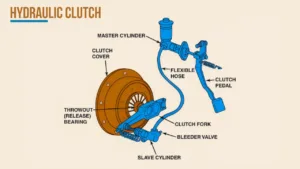
Hydraulic Clutch Explained: Diagram, Function, and Easy Bleeding Guide A hydraulic clutch is an essential component in modern vehicles, offering smoother and more efficient control...
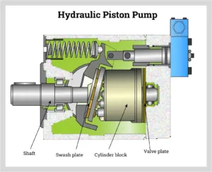
What is a Hydraulic Pump and How Does It Work? – 2025 Guide Hydraulic systems are integral to many industries, from construction and manufacturing to...
How Does a Hydraulic Jack Work? Types, Functionality, and Diagram Explained (2025 Guide) Hydraulic jacks are among the most commonly used tools for lifting heavy...
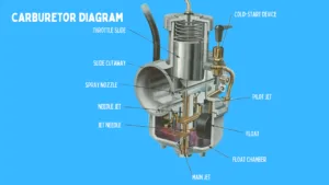
A carburetor is a critical component in older internal combustion engines, particularly in vehicles manufactured before the widespread adoption of fuel injection systems. It plays...
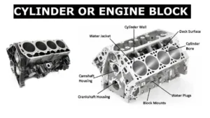
What Is a Cylinder Block and Cylinder Liner? Types of Liners Explained In the world of internal combustion engines, understanding the cylinder block and cylinder...